
 Image 1 of 3
 Image 2 of 3
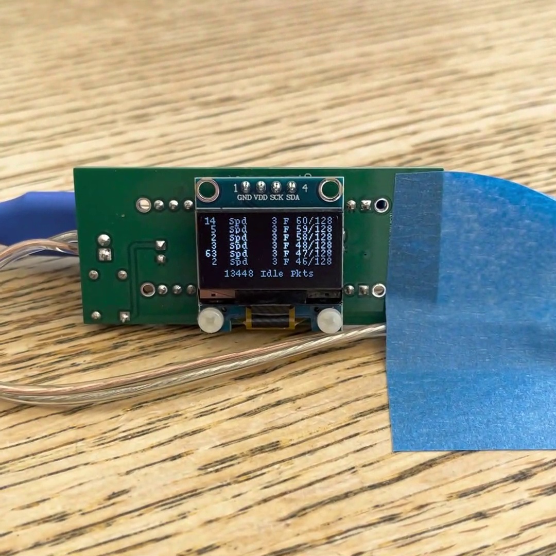 Image 3 of 3
DCC Monitor Shield Theory of Operation
The intent of this Shield and Sketch combination is to illustrate issues embedded engineers encounter in performance of their job. Along the way we created a useful device for monitoring model train DCC commands. These are commands that adhere to the National Model Railroad Association (NMRA) Digital Command Control (DCC) standards.
All power is provided by the DCC differential power found on the train track rails. The Shield consists of a few distinct power modules and the signal sense module.
Main Power
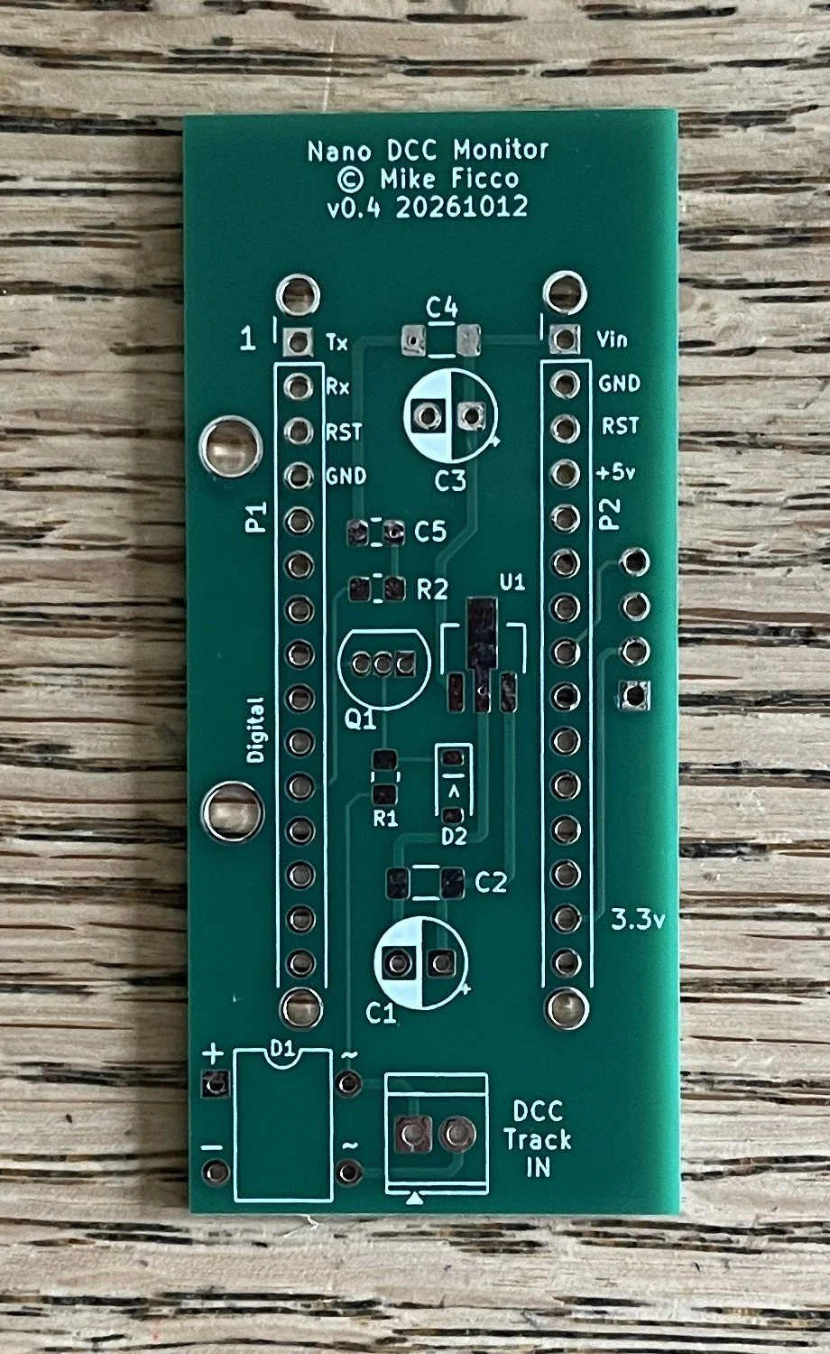
The track rails take turns providing voltage. Depending on the model train system, the available voltage can range from a low of maybe 12 volts to over 20 volts. Voltages over 20 volts will shorten the life of this Shield. It's not made for that, so keep the input voltage below about 20 volts. Both the rails of the track only provide a positive voltage but to the wiring on the Shield it looks like alternating current and must be rectified to DC. The bridge rectifier, D1, does that. Capacitors C1 and C2 smooth the rectifier output and this smoothed output goes to voltage regulator, U1, which does its job and outputs 9 volts. That output is smoothed by capacitors C3 and C4 to provide a quality 9 volts to the Arduino Nano Vin pin. This fully powers the Nano and the friendly Nano in turn provides 5 volts and 3.3 volts for use by the Shield.
Nano +5v Power
This is used on the Shield as a pullup, through resistor R2, for transistor Q1. This creates a voltage level shifter from the DCC voltage on the rail to the +5v of the Arduino.
Nano +3.3v Power
This powers the OLED display.
Signal Sensing
The basic problem is the track rail voltages are 12 or 15 or whatever volts and the Arduino doesn't like anything over 5 volts. Transistor Q1 acts as a voltage level shifter and isolates the Arduino from the vagrancies of the track voltage. The output of Q1 is fed into Arduino digital pin 8 where Timer 1 uses Input Capture Mode to measure the incoming bit pulse widths and determine whether the bit is a zero or one. The Sketch assembles entire DCC command packets using a simple state machine.